
Image Specifications – Threaded Fastener Assembly Surface Condition & Corrosion Documentation
Camera: Canon EOS 5D Mark IV
Lens: 2× Macro Lens
Exposure Settings:
ISO: 100
Aperture: f/13 (selected to preserve depth-of-field across hex head geometry, thread profiles, and corrosion features)
Shutter Speed: 1/160 sec
Focus Stacking:
Number of Frames: 18 images (to maintain full depth-of-field across threads, hex faces, and localized corrosion)
Lighting:
Cygnustech-diffused on-camera flash (Speedlite)
Tripod-mounted camera
Macro focusing rail for controlled focus advancement
Remote release / timer to eliminate vibration
Processing:
Focus stack composited in Adobe Photoshop
Tonal normalization and clarity adjustments applied for accurate surface and corrosion representation
No retouching or structural alteration applied

Threaded Fastener Assembly – Macro Failure Analysis Documentation
Component: Threaded fastener with integrated washer
Application: Mechanical assembly fastener (automotive / power equipment–type hardware)
Study Type: Non-destructive visual inspection (macro imaging)
Imaging Objective
Document the surface condition, thread integrity, and material state of a threaded fastener recovered from service or storage to support failure analysis, corrosion assessment, and engineering evaluation.
Imaging Methodology
High-resolution macro photography was performed using diffused strobe illumination to control specular highlights on metallic surfaces. Multi-frame focus stacking was applied to achieve full depth-of-field across thread geometry, washer interface, and fastener head features. Imaging was conducted in an as-received condition prior to cleaning or mechanical alteration.
Observations
Thread geometry appears intact with no evidence of shear failure or thread stripping.
Surface oxidation and discoloration are present across thread faces and washer surfaces, consistent with environmental exposure or long-term storage.
Localized surface pitting and texture variation observed along the threads.
Washer exhibits uneven wear patterns and surface contamination.
No visible cracking, fracture, or gross deformation of the fastener head or threaded section.
Engineering Interpretation
Visual evidence suggests material degradation driven by corrosion and environmental exposure rather than mechanical overload or installation-related failure. Thread engagement features remain structurally intact, indicating the fastener likely retained functional integrity prior to removal. Observed surface condition may contribute to increased friction, torque variation, or reduced service life if reused.
Use Case
Images used to support:
Non-destructive failure analysis
Corrosion and surface condition assessment
Root-cause hypothesis development
Engineering documentation and teardown records
Notes
This documentation does not include dimensional measurement, torque testing, or metallurgical analysis. No digital modifications affecting structural interpretation were applied beyond focus stack compositing and tonal normalization.
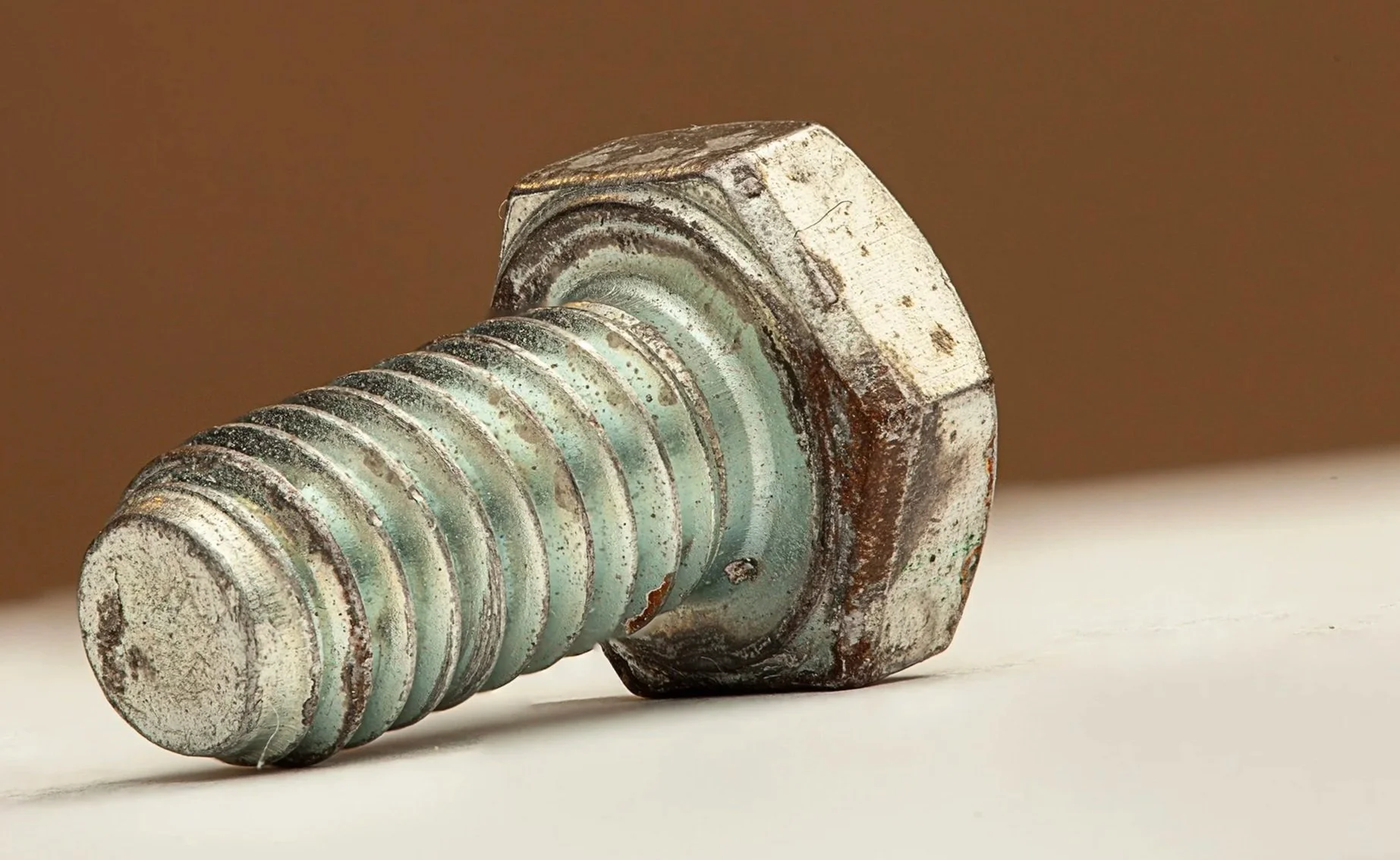
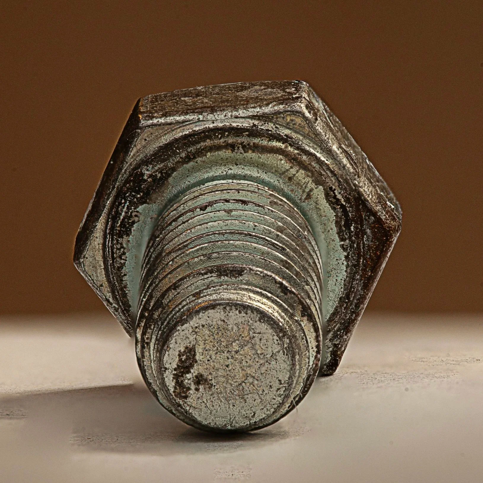
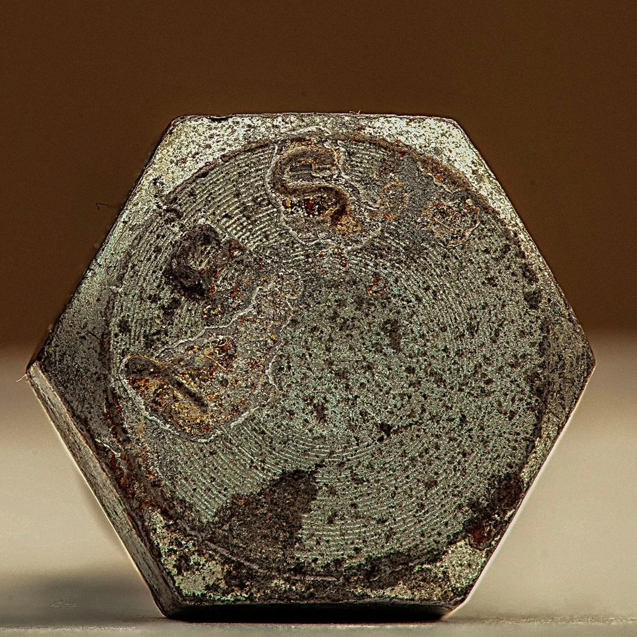
Image Specifications – Hex Head Bolt Macro Surface Condition & Corrosion Documentation
Camera: Canon EOS 5D Mark IV
Lens: 2× Macro Lens
Exposure Settings:
ISO: 100
Aperture: f/13 (selected to preserve depth-of-field across hex head geometry, thread profiles, and corrosion features)
Shutter Speed: 1/160 sec
Focus Stacking:
Number of Frames: 18 images (to maintain full depth-of-field across threads, hex faces, and localized corrosion)
Lighting:
Cygnustech-diffused on-camera flash (Speedlite)
Tripod-mounted camera
Macro focusing rail for controlled focus advancement
Remote release / timer to eliminate vibration
Processing:
Focus stack composited in Adobe Photoshop
Tonal normalization and clarity adjustments applied for accurate surface and corrosion representation
No retouching or structural alteration applied
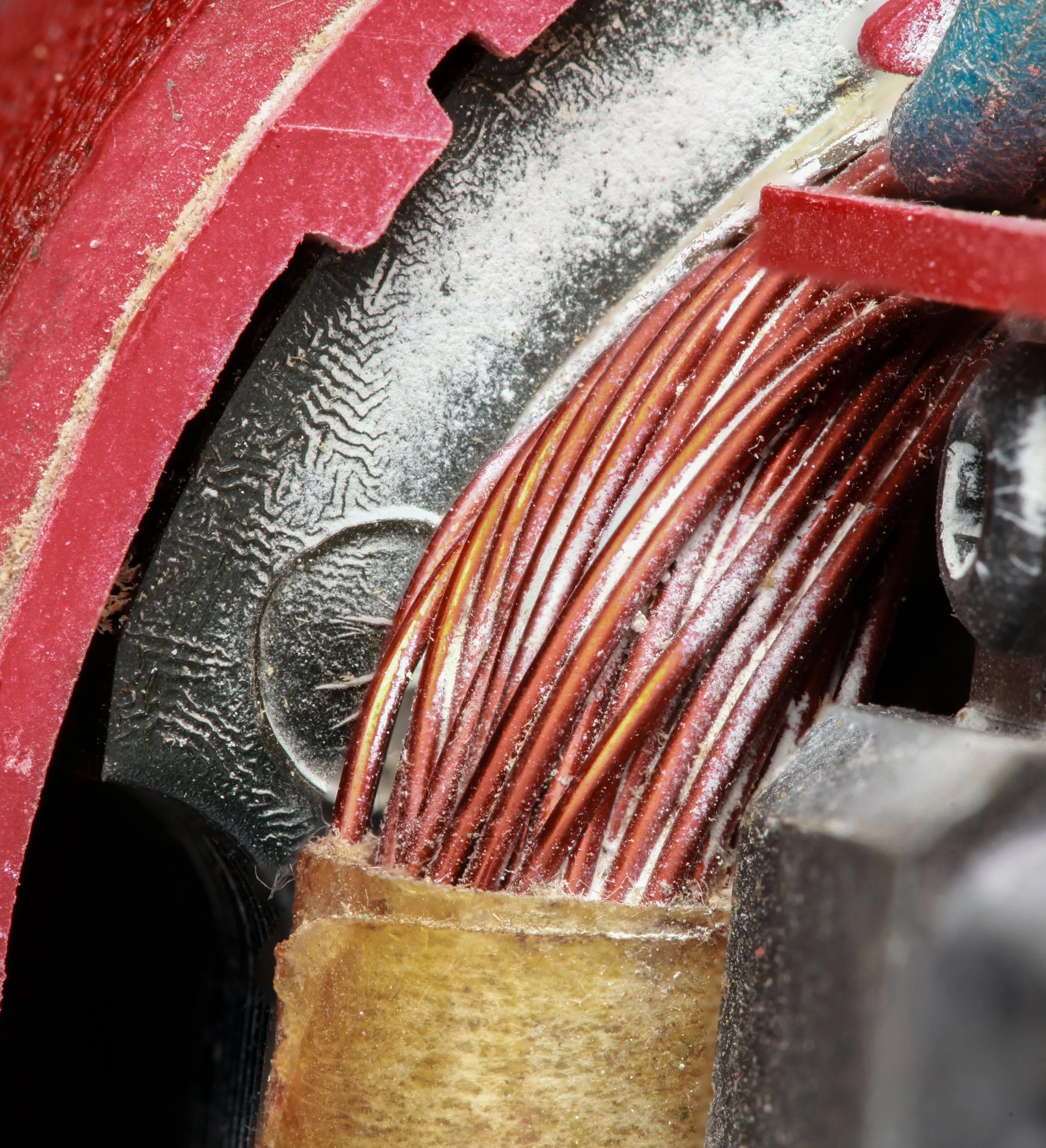

Electric Motor Winding Assembly – Macro Failure Analysis Documentation
Component: Electric motor copper winding assembly
Application: Power tool motor (representative electric motor architecture)
Study Type: Non-destructive visual inspection (macro imaging) from three different perspectives.
Imaging Objective
Document the condition of the copper winding assembly to facilitate failure analysis, material evaluation, and engineering review
Imaging Methodology
High-resolution macro photography was performed using controlled, diffused strobe illumination with cross-polarization to minimize specular reflection from conductive surfaces. Multi-frame focus stacking was applied to achieve full depth-of-field across the winding geometry and adjacent components. Imaging was conducted with the component in an as-received condition.
Observations
Copper windings appear continuous with no visible fracture, burn-through, or arc damage.
Enamel insulation shows no obvious blistering, peeling, or thermal degradation.
Winding geometry and coil spacing remain uniform with no evidence of displacement or mechanical deformation.
Light particulate contamination is present on winding surfaces and surrounding housing, consistent with environmental exposure or long-term storage.
Adjacent resin and insulating materials appear intact with no visible cracking or charring.
Engineering Interpretation
Macro documentation supports elimination of catastrophic electrical winding failure as a primary failure mode. Visual evidence suggests the component remained structurally intact, indicating potential failure origin external to the winding assembly (e.g., bearings, commutation system, electrical control, or duty-cycle exceedance).
Use Case
Images used to support:
Non-destructive failure analysis
Root-cause hypothesis development
Engineering review and technical reporting
Pre-teardown documentation baseline
Notes
This documentation does not include dimensional measurement or electrical performance testing. No digital alteration affecting structural interpretation was applied beyond focus stack compositing and tonal normalization.
Image Specifications –
Carburetor Component Macro Study
Camera: Canon EOS 5D Mark IV
Lens: Canon 24-70mm
Exposure Settings:
ISO: 100
Aperture: f/13 (to maximize depth on metallic structures)
Shutter Speed: 1/160 sec
Focus Stacking: 15 images
Lighting: Macro Photography Flash Diffuser with Speedlite Flash Diffuser Softbox to manage harsh reflections and sculpt highlights
Stability: Tripod-mounted; timer; macro rail
Processing: Focus stack blended in Adobe Photoshop; contrast and clarity enhanced for technical accuracy
Mechanical Cable Assembly – Engineering Evaluation & Functional Testing Specification
Component: Mechanical cable-actuated circular assembly
Material: Steel housing with steel cable and mixed metallic subcomponents
Application Context: Mechanical actuation / tensioning system (automotive or industrial)
Study Type: Engineering inspection and non-destructive functional assessment
OEM Context: Stellantis-style legacy component evaluation and teardown documentation
Testing Objective
Evaluate the structural integrity, surface condition, and functional readiness of a mechanical cable assembly recovered from service or storage. Testing is intended to identify wear mechanisms, degradation patterns, and potential performance risks prior to reuse, refurbishment, or comparative analysis.
Inspection & Test Methodology
1. Visual & Macro Inspection (Non-Destructive)
High-resolution macro imaging used to document:
Cable routing and winding consistency
Crimp terminations and attachment points
Housing geometry and concentric alignment
Surface oxidation, residue, and wear patterns
Inspection performed in as-received condition with no cleaning or mechanical manipulation prior to documentation.
2. Manual Actuation Assessment
Cable manually tensioned through full available travel range (where accessible).
Observations recorded for:
Smoothness of motion
Binding, hesitation, or uneven resistance
Audible mechanical noise indicative of internal interference
3. Rotational / Hub Evaluation
Central hub or rotating element assessed for:
Free rotation consistency
Axial or radial play
Evidence of bearing surface degradation
4. Surface Condition Assessment
Oxidation levels visually categorized (light / moderate / advanced).
Localized wear at cable contact points and guide surfaces documented.
Residue presence evaluated for potential contamination-related friction increase.
Observed Conditions (Representative)
Cable remains continuously wound with no visible strand separation or catastrophic fraying.
Crimped cable ends appear mechanically intact with localized coating loss.
Housing exhibits uniform concentric geometry with no visible deformation.
Surface oxidation present on exposed metallic surfaces, consistent with age-related environmental exposure.
Residue accumulation observed within recessed areas, potentially contributing to increased friction.
Engineering Interpretation
Observed conditions indicate progressive wear and environmental degradation consistent with extended service life rather than acute mechanical failure. Cable integrity appears maintained; however, surface oxidation and residue accumulation may adversely affect actuation smoothness, load consistency, and long-term reliability.
While no immediate structural failure indicators are present, functional performance under load cannot be fully validated without controlled force, cycle, and endurance testing.
Recommended Follow-Up Testing (If Required)
Cable tension load testing to verify elastic behavior and load retention
Cycle testing to evaluate wear progression under repeated actuation
Disassembly-based inspection for internal wear surface evaluation
Lubrication response testing to assess friction reduction potential
Image Specifications –
Mechanical Cable Assembly Macro Study
Camera: Canon EOS 5D Mark IV
Lens: Canon 24-70mm
Exposure Settings:
ISO: 100
Aperture: f/13 (to maximize depth on metallic structures)
Shutter Speed: 1/160 sec
Focus Stacking: 15 images
Lighting: Macro Photography Flash Diffuser with Speedlite Flash Diffuser Softbox to manage harsh reflections and sculpt highlights
Stability: Tripod-mounted; timer; macro rail
Processing: Focus stack blended in Adobe Photoshop; contrast and clarity enhanced for technical accuracy

Dime – Macro Surface Condition & Component Documentation
Component: Dime (U.S. 10-cent coin)
Material: Clad metal composition (Copper core with nickel coating)
Application Context: Circulating currency, collector evaluation, and numismatic study
Study Type: Non-destructive visual inspection (macro imaging)
OEM Context: Stellantis-style engineering documentation
Imaging Objective
Document the surface condition, strike integrity, and visible wear characteristics of a dime in as-received circulated condition to support numismatic assessment, wear analysis, and archival documentation. Imaging aims to capture edge detail, obverse/reverse relief, and surface features without mechanical handling that could alter condition.
Imaging Methodology
High-resolution macro photography was performed using controlled, diffused strobe lighting to manage reflections on metallic surfaces. Multi-frame focus stacking was applied to maintain full depth-of-field across convex and concave regions, rim edges, lettering, and relief features. Imaging was conducted prior to any cleaning or polishing to preserve original condition and evidence of circulation.
Visual Observations
Obverse (front) and reverse (back) surfaces exhibit legible relief elements with minor flattening on high points consistent with circulation wear.
Edge reeding remains largely intact, with localized smoothing on contact points.
Surface exhibits uniform oxidation and toning, consistent with environmental exposure and handling.
Minor scratches, nicks, and microabrasions present across both faces, predominantly along the rim and raised relief areas.
No structural deformation, cracks, or evidence of corrosion-induced delamination observed.
Engineering Interpretation
Observed conditions indicate gradual surface degradation and abrasion consistent with normal circulation wear rather than acute damage. Oxidation and toning patterns suggest exposure to typical environmental conditions. Surface wear may slightly reduce visual relief detail but does not compromise structural integrity. Visual evidence supports further metallurgical or numismatic analysis if grading, authentication, or compositional verification is required.
Use Case
Images support:
Non-destructive numismatic inspection
Circulation wear assessment
Archival documentation of coins for reference or comparison
Collector grading or historical analysis
Notes & Limitations
This documentation reflects surface-level visual analysis only. No compositional testing, hardness measurement, or metallurgical analysis was performed. Image processing was limited to focus stack compositing and tonal normalization; no alterations affecting structural interpretation were applied.
Image Specifications –
Dime (Front & Back) Macro Study
Camera: Canon EOS 5D Mark IV
Lens: Macro lens 100mm macro
Exposure Settings:
ISO: 100
Aperture: f/10
Shutter Speed: 1/160 sec
Focus Stacking: 10 images per side
Lighting: Macro Photography Flash Diffuser with Speedlite Flash Diffuser Softbox to manage harsh reflections and sculpt highlights
Stability: Tripod-mounted; timer; macro rail
Processing: Focus stacks blended in Adobe Photoshop; front and back aligned and finished for presentation
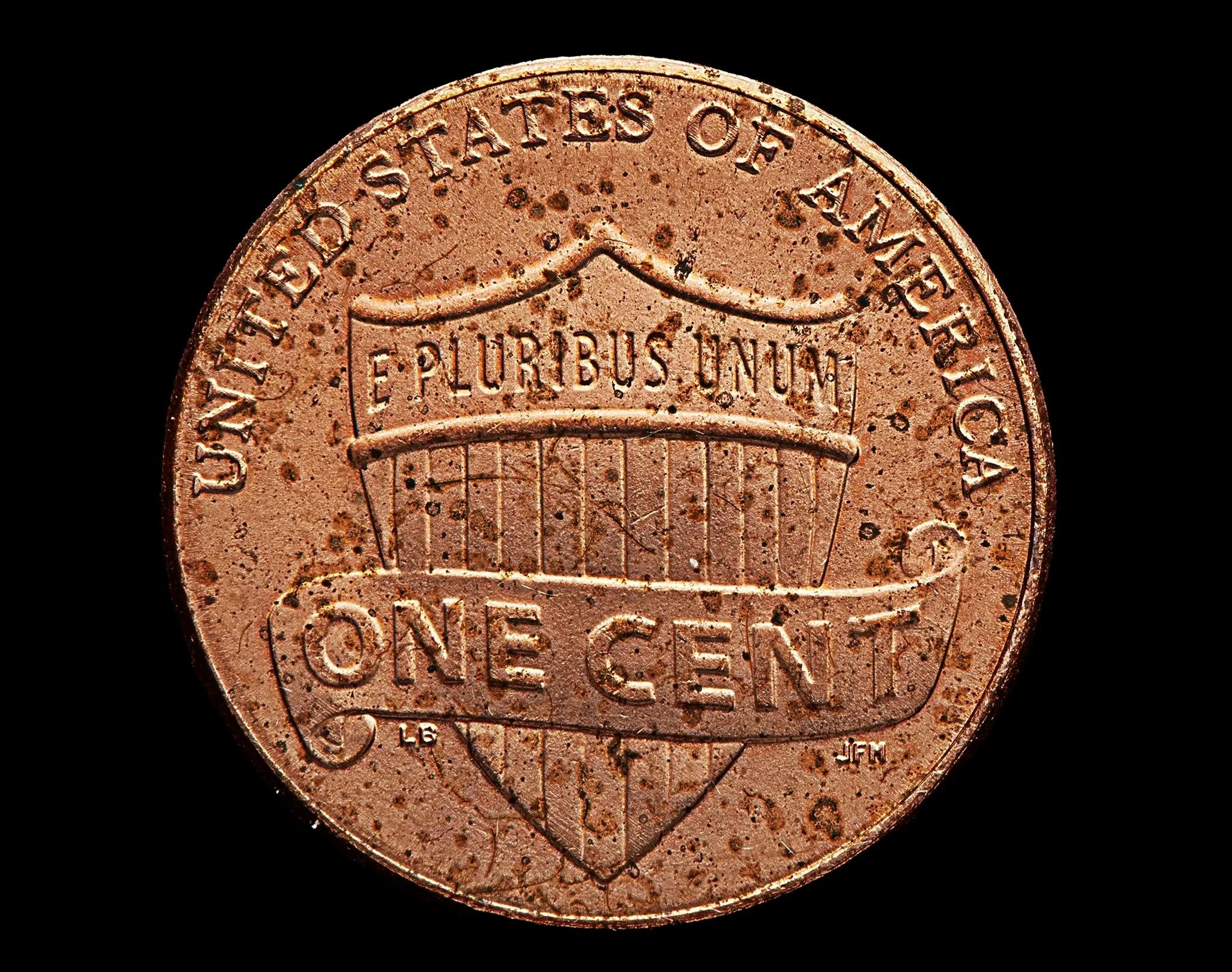
Copper Penny – Macro Surface Condition & Component Documentation
Component: Copper penny (U.S. 1-cent coin)
Material: Copper-plated zinc (post-1982) or solid copper (pre-1982)
Application Context: Circulating currency, collector evaluation, and numismatic study
Study Type: Non-destructive visual inspection (macro imaging)
OEM Context: Stellantis-style engineering documentation
Imaging Objective
Document the surface condition, strike integrity, and visible wear characteristics of a copper penny in as-received circulated condition to support numismatic assessment, wear analysis, and archival documentation. Imaging captures obverse/reverse relief, edge detail, and surface features without mechanical handling that could alter condition.
Imaging Methodology
High-resolution macro photography was performed using controlled, diffused strobe lighting to manage reflections across metallic surfaces. Multi-frame focus stacking was applied to preserve full depth-of-field across convex relief areas, lettering, rim edges, and minor surface imperfections. Imaging was conducted prior to any cleaning or polishing to preserve original condition and circulation evidence.
Visual Observations
Obverse and reverse surfaces exhibit high points with partial flattening and minor smoothing consistent with circulation wear.
Edge remains uniform, with localized nicks and abrasions along rim contact points.
Surface displays uniform oxidation, patina, and toning consistent with environmental exposure and handling.
Minor scratches, microabrasions, and contact marks present across both faces, predominantly along raised relief areas.
No cracks, delamination, or catastrophic structural deformation observed.
Engineering Interpretation
Observed conditions suggest gradual surface degradation and abrasion consistent with standard circulation rather than acute damage. Patina and oxidation indicate environmental exposure over time. Surface wear may reduce the sharpness of design relief but does not compromise structural integrity. Visual evidence supports further numismatic evaluation or metallurgical analysis if grading, authentication, or compositional verification is required.
Use Case
Images support:
Non-destructive numismatic inspection
Circulation wear and condition assessment
Archival documentation for reference or comparison
Collector grading and historical analysis
Notes & Limitations
This documentation reflects surface-level visual analysis only. No compositional testing, hardness measurement, or metallurgical analysis was performed. Image processing was limited to focus stack compositing and tonal normalization; no alterations affecting structural interpretation were applied.
Image Specifications –
Copper Penny Macro Study
Camera: Canon EOS 5D Mark IV
Lens: Macro lens 100mm macro
Exposure Settings:
ISO: 100
Aperture: f/11
Shutter Speed: 1/160 sec
Focus Stacking: 10 images
Lighting: Macro Photography Flash Diffuser with Speedlite Flash Diffuser Softbox to manage harsh reflections and sculpt highlights
Stability: Tripod-mounted; timer; macro rail
Processing: Focus stack blended in Adobe Photoshop; minimal surface correction to retain intentional imperfections
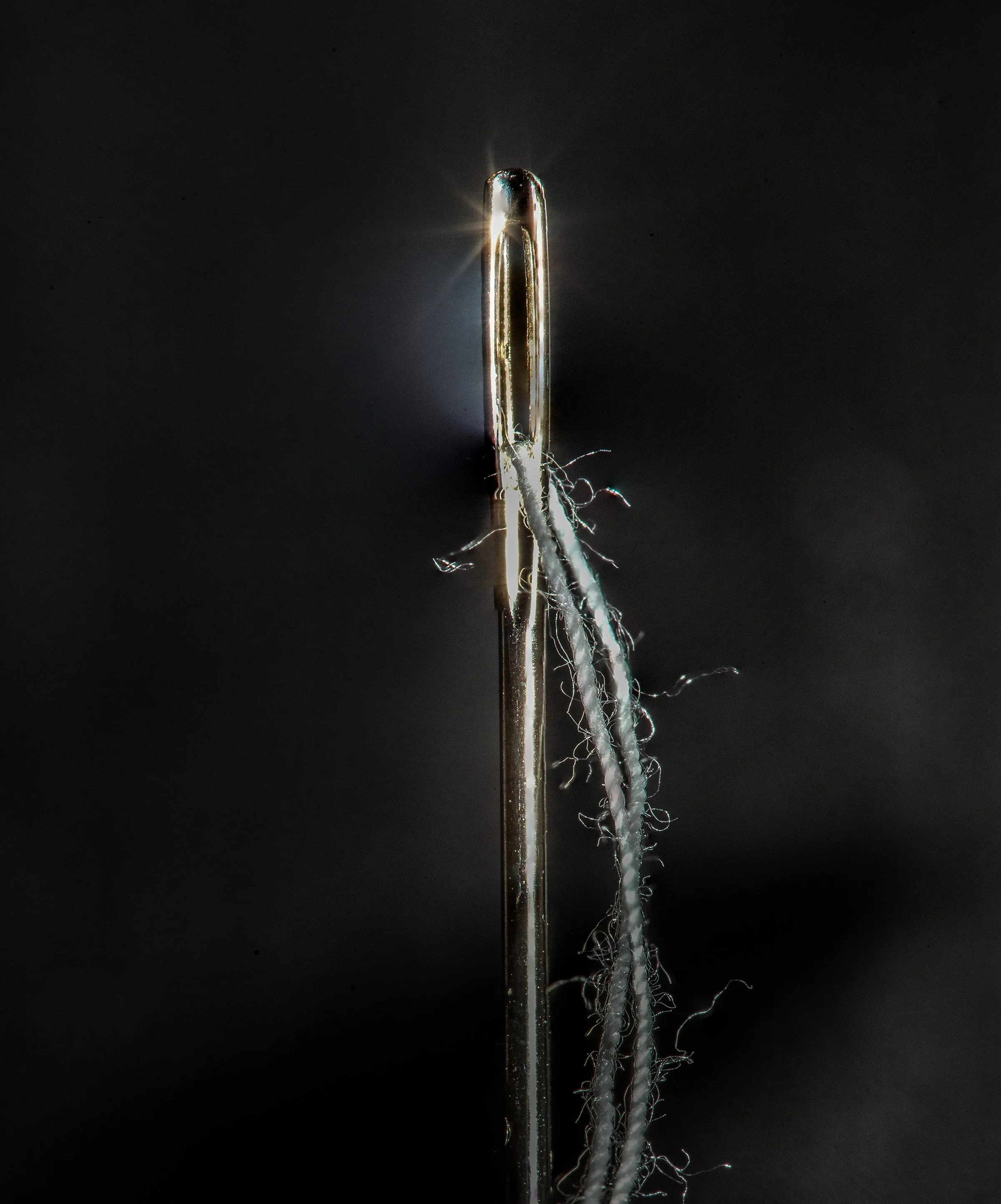
Threaded Needle – Macro Surface Condition & Component Documentation
Component: Threaded needle (sewing or medical application)
Material: Stainless steel needle body with textile fiber thread
Application Context: Stitching, sewing, or precise assembly applications
Study Type: Non-destructive visual inspection (macro imaging)
OEM Context: Stellantis-style engineering documentation
Imaging Objective
Document the surface condition, thread integrity, and needle body defects in as-received condition to support component evaluation, serviceability assessment, and quality review. Imaging captures thread shredding, needle pitting, and surface irregularities without mechanical manipulation that could alter original condition.
Imaging Methodology
High-resolution macro photography was performed using controlled, diffused strobe lighting to minimize specular reflections on metallic surfaces and fibers. Multi-frame focus stacking was applied to preserve full depth-of-field across the needle shaft, threaded sections, and fiber texture. Imaging was conducted prior to cleaning or manipulation to maintain original condition and evidence of wear or manufacturing defects.
Visual Observations
Needle body exhibits localized pitting and surface imperfections along the shaft, with minor scratches consistent with handling or operational use.
Thread shows shredding, fraying, and partial separation of fiber strands along threaded sections, indicative of stress or wear.
Thread remains largely attached to the needle but exhibits reduced tensile integrity in high-wear areas.
Tip geometry remains largely intact; minor rounding observed on points consistent with operational contact.
No catastrophic bending, cracking, or complete thread failure observed.
Engineering Interpretation
Observed conditions suggest operational wear and gradual degradation of the thread rather than acute mechanical failure. Pitting on the needle body may result from environmental exposure, material inconsistencies, or repeated contact stresses. Thread fraying indicates potential tensile weakening, which may affect stitching quality or precision application. Visual evidence supports further functional testing or replacement evaluation if performance degradation is suspected.
Use Case
Images support:
Non-destructive component inspection
Thread and needle wear assessment
Quality assurance documentation
Manufacturing defect or serviceability review
Notes & Limitations
This documentation reflects surface-level visual analysis only. No tensile testing, metallurgical composition analysis, or microscopic fiber analysis was performed. Image processing was limited to focus stack compositing and tonal normalization; no alterations affecting structural interpretation were applied.
Image Specifications –
Threaded Needle Macro Study
Camera: Canon EOS 5D Mark IV
Lens: Macro lens 100mm macro
Exposure Settings:
ISO: 100
Aperture: f/16 (to maximize depth of field along the needle and thread)
Shutter Speed: 1/125 sec
Focus Stacking: 18 images
Lighting: Macro Photography Flash Diffuser with Speedlite Flash Diffuser Softbox to manage harsh reflections and sculpt highlights. Controlled diffused light with intentional light burst highlighting the needle eye
Stability: Tripod-mounted; timer; macro rail
Processing: Focus stack blended in Adobe Photoshop; light burst emphasized without compromising detail

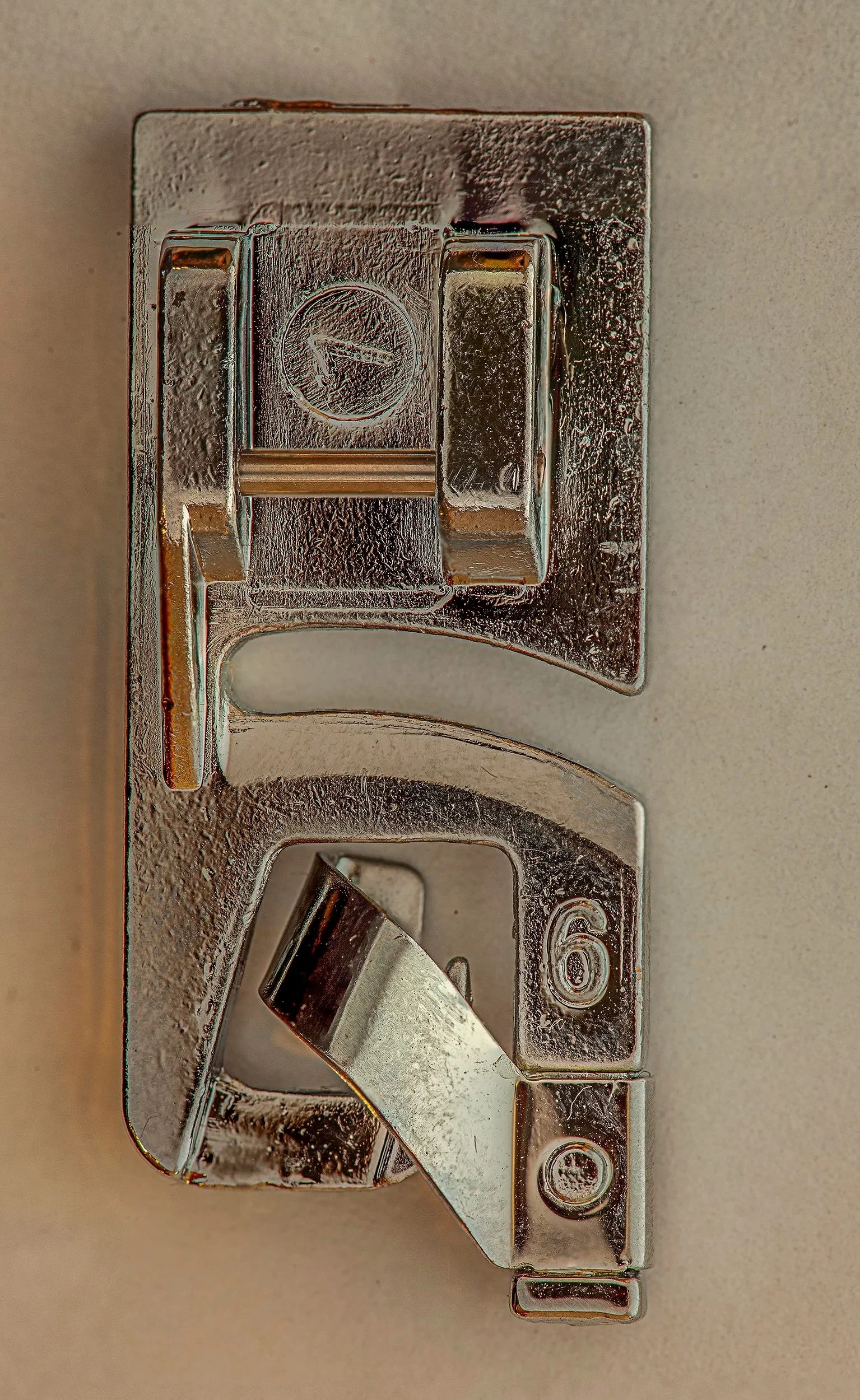
Rolled Hem Sewing Presser Foot – Macro Surface Condition & Component Documentation
Component: Rolled hem sewing presser foot
Material: Stainless steel with nickel or chrome plating
Application Context: Sewing machine attachment for producing precise rolled hems in fabric
Study Type: Non-destructive visual inspection (macro imaging)
OEM Context: Stellantis-style engineering documentation
Imaging Objective
Document the surface condition, attachment integrity, and wear characteristics of a rolled hem presser foot in as-received condition to support component evaluation, serviceability assessment, and quality inspection. Imaging captures contact surfaces, guide channels, and plated finish without mechanical manipulation that could alter original condition.
Imaging Methodology
High-resolution macro photography was performed using controlled, diffused strobe lighting to manage reflections on metallic surfaces. Multi-frame focus stacking was applied to preserve full depth-of-field across the foot base, guide slot, and heel surface. Imaging was conducted prior to cleaning or mechanical handling to preserve original condition and evidence of use or wear.
Visual Observations
Base and guide surfaces exhibit minor wear along fabric contact areas, consistent with operational use.
Plated finish remains largely intact with localized scratches and slight dulling of high-contact zones.
Screw threads and attachment points are intact with minimal coating loss; no stripped threads observed.
Guide channel shows minor micro-abrasions consistent with fabric friction during hemming operations.
No structural deformation, cracks, or catastrophic material failure observed.
Engineering Interpretation
Observed conditions suggest gradual surface wear consistent with standard operational use rather than acute damage. Minor scratches and coating dulling may minimally affect fabric glide and hem precision but do not compromise structural integrity. Visual evidence supports continued use or cleaning-based maintenance; further functional testing may be warranted if hem quality is degraded.
Use Case
Images support:
Non-destructive component inspection
Operational wear assessment
Quality control and serviceability review
Reference for replacement evaluation
Notes & Limitations
This documentation reflects surface-level visual analysis only. No dimensional metrology, hardness testing, or friction analysis was performed. Image processing was limited to focus stack compositing and tonal normalization; no alterations affecting structural interpretation were plied.
Image Specifications –
Sewing Machine Foot Macro Study
Camera: Canon EOS 5D Mark IV
Lens: Macro lens 100mm macro
Exposure Settings:
ISO: 100
Aperture: f/11 (to ensure full depth of field across the foot)
Shutter Speed: 1/160 sec
Focus Stacking: 26 images
Lighting: Macro Photography Flash Diffuser with Speedlite Flash Diffuser Softbox to manage harsh reflections and sculpt highlights. Soft diffused lighting to prevent blowouts while highlighting surface textures and wear
Stability: Tripod-mounted; timer; macro real
Processing: Focus stack blended in Adobe Photoshop; contrast enhanced to reveal surface damage without clipping highlights
Click here to return to the portfolio pages