Mechanical Cable Assembly – Functional Inspection
Component: Cable-actuated circular assembly
Material: Steel housing with steel cable and metallic subcomponents
Objective
Assess structural condition, wear characteristics, and functional readiness of a cable-actuated mechanical assembly through visual inspection and manual actuation.
Inspection Method
High-resolution macro imaging used to document cable routing, crimp terminations, housing alignment, and surface condition. Manual actuation performed to evaluate cable movement and resistance.
Observed Condition
Cable remains continuously wound with no visible strand separation or major fraying. Crimp terminations appear intact with localized coating loss. Housing geometry remains uniform with no visible deformation. Surface oxidation and residue accumulation are present on exposed metal surfaces.
Engineering Interpretation
Observed oxidation and residue are consistent with environmental exposure and extended service life. No immediate structural failure indicators were identified; however, performance under operational load would require further testing.
Surface Wear & Failure Analysis
Metal Surface Corrosion – Material Degradation
Purpose
Document corrosion patterns for engineering analysis and quality review.
Technique
Macro capture with directional lighting to reveal oxidation texture and surface irregularities.
Engineering Value
Useful for durability studies, supplier quality investigation, and failure analysis documentation
Figure — Corroded Hex Bolt Surface Condition
Purpose
Document corrosion, oxidation, and wear patterns on a threaded hex bolt to demonstrate inspection-level macro imaging used for evaluating fastener condition.
Technique
High-magnification macro imaging with controlled directional lighting to reveal thread geometry, surface texture, and corrosion deposits.
Testing Notes
Visible oxidation and corrosion are present across the bolt head and threaded shaft. Corrosion accumulation is concentrated along the thread valleys and near the head interface. Surface pitting and oxidation partially obscure stamped markings on the bolt head. Directional lighting enhances visibility of thread geometry and corrosion distribution for inspection documentation.
Wiring Harness Study
Imaging Objective
Document connector interface and wiring routing for engineering inspection.
Imaging Methodology
High-resolution macro capture with diffused lighting to reduce specular
reflections on insulation surfaces.
Visual Observations
• Wiring insulation intact
• Connector housings undamaged
• Minor abrasion at routing points
Engineering Interpretation
Observed wear consistent with normal operational vibration.
Use Case
Supports inspection documentation and service manual reference.
Figure — Presser Foot Mechanical Contact Wear
Purpose
Document wear patterns and surface condition on a sewing machine presser foot to demonstrate inspection-level macro imaging of components subjected to repeated mechanical contact.
Technique
High-magnification macro imaging with controlled directional lighting to reveal contact polishing, abrasion marks, and reflective surface texture.
Testing Notes
The presser foot exhibits localized polishing and abrasion along the lower contact surface consistent with repeated engagement against fabric and feed mechanisms during operation. Directional lighting enhances visibility of the wear zone and reveals subtle surface texture variations that indicate long-term mechanical contact and frictional interaction.
Image Specifications –
Camera: Canon EOS 5D Mark IV
Lens: Canon 24-70mm
Exposure Settings:
ISO: 100
Aperture: f/13 (to maximize depth on metallic structures)
Shutter Speed: 1/160 sec
Focus Stacking: 15 images
Lighting: Macro Photography Flash Diffuser with Speedlite Flash Diffuser Softbox to manage harsh reflections and sculpt highlights
Stability: Tripod-mounted; timer; macro rail
Processing: Focus stack blended in Adobe Photoshop; contrast and clarity enhanced for technical accuracy
Figure 2 – Mechanical Cable Assembly
Image Specifications –
Mechanical Cable Assembly Macro Study
Camera: Canon EOS 5D Mark IV
Lens: Canon 24-70mm
Exposure Settings:
ISO: 100
Aperture: f/13 (to maximize depth on metallic structures)
Shutter Speed: 1/160 sec
Focus Stacking: 15 images
Lighting: Macro Photography Flash Diffuser with Speedlite Flash Diffuser Softbox to manage harsh reflections and sculpt highlights
Stability: Tripod-mounted; timer; macro rail
Processing: Focus stack blended in Adobe Photoshop; contrast and clarity enhanced for technical accuracy
Figure 3 – Composite Friction Surface Wear

Figure 6– Coiled Hex Screw Assembly
Image Specifications – Hex Bolt Surface Corrosion Documentation
Camera: Canon EOS 5D Mark IV
Lens: 2× Macro Lens
Exposure: ISO 100 • f/13 • 1/160 sec
Focus Method: 18-frame extended depth-of-field macro stack
Lighting: Diffused Cygnustech Speedlite flash
Stabilization: Tripod, macro focusing rail, remote release
Processing: Focus stack composited in Adobe Photoshop with tonal normalization and clarity adjustments. No structural alterations applied.


Figure 9- Wiring Harness Study

Image Specifications – Hex Bolt Surface Corrosion Documentation
Camera: Canon EOS 5D Mark IV
Lens: 2× Macro Lens
Exposure: ISO 100 • f/13 • 1/160 sec
Focus Method: 18-frame extended depth-of-field macro stack
Lighting: Diffused Cygnustech Speedlite flash
Stabilization: Tripod, macro focusing rail, remote release
Processing: Focus stack composited in Adobe Photoshop with tonal
normalization and clarity adjustments. No structural alterations applied.
Figure 7 - Hex Bolt
Figure — Threaded Fastener Dimensional Inspection
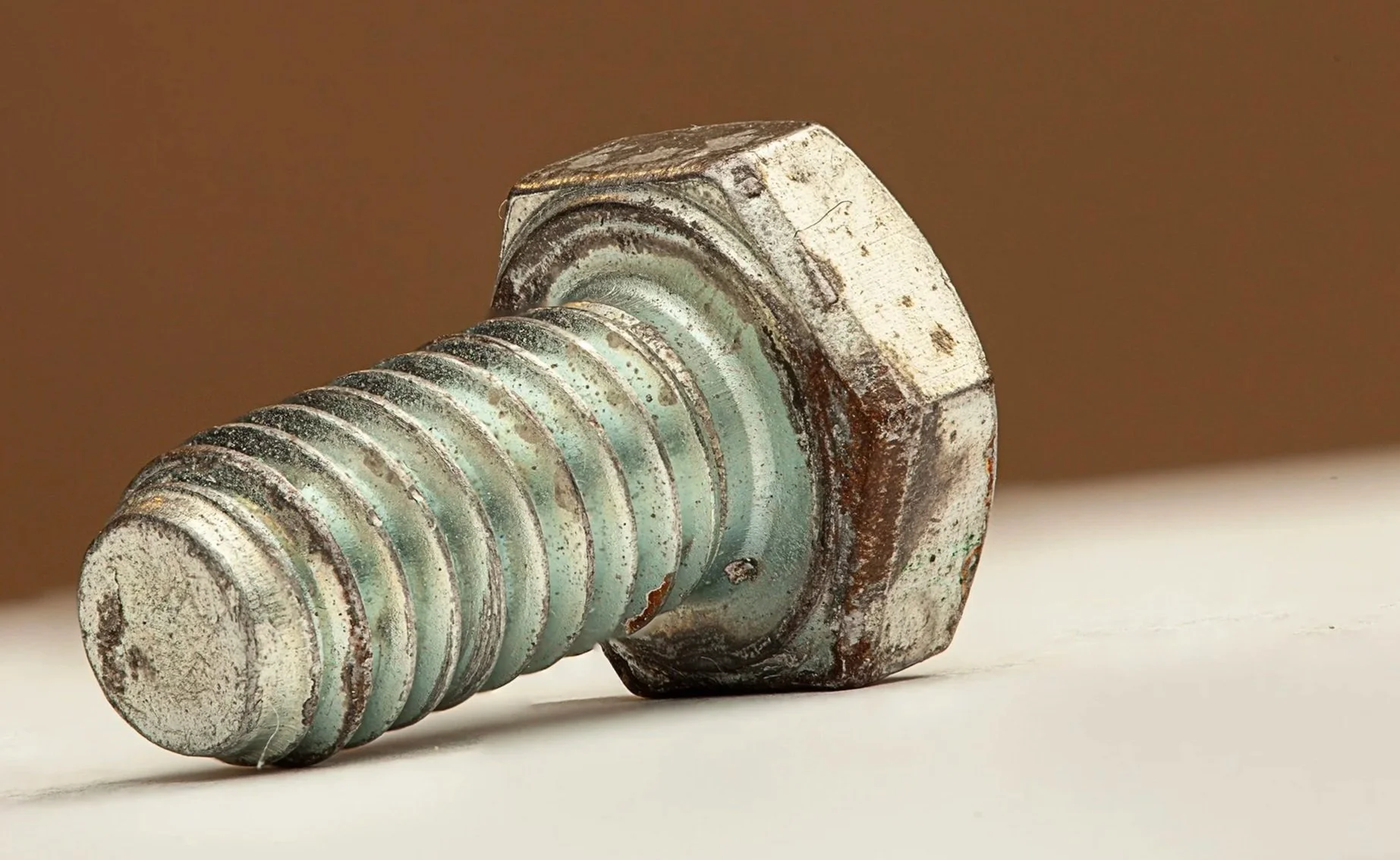
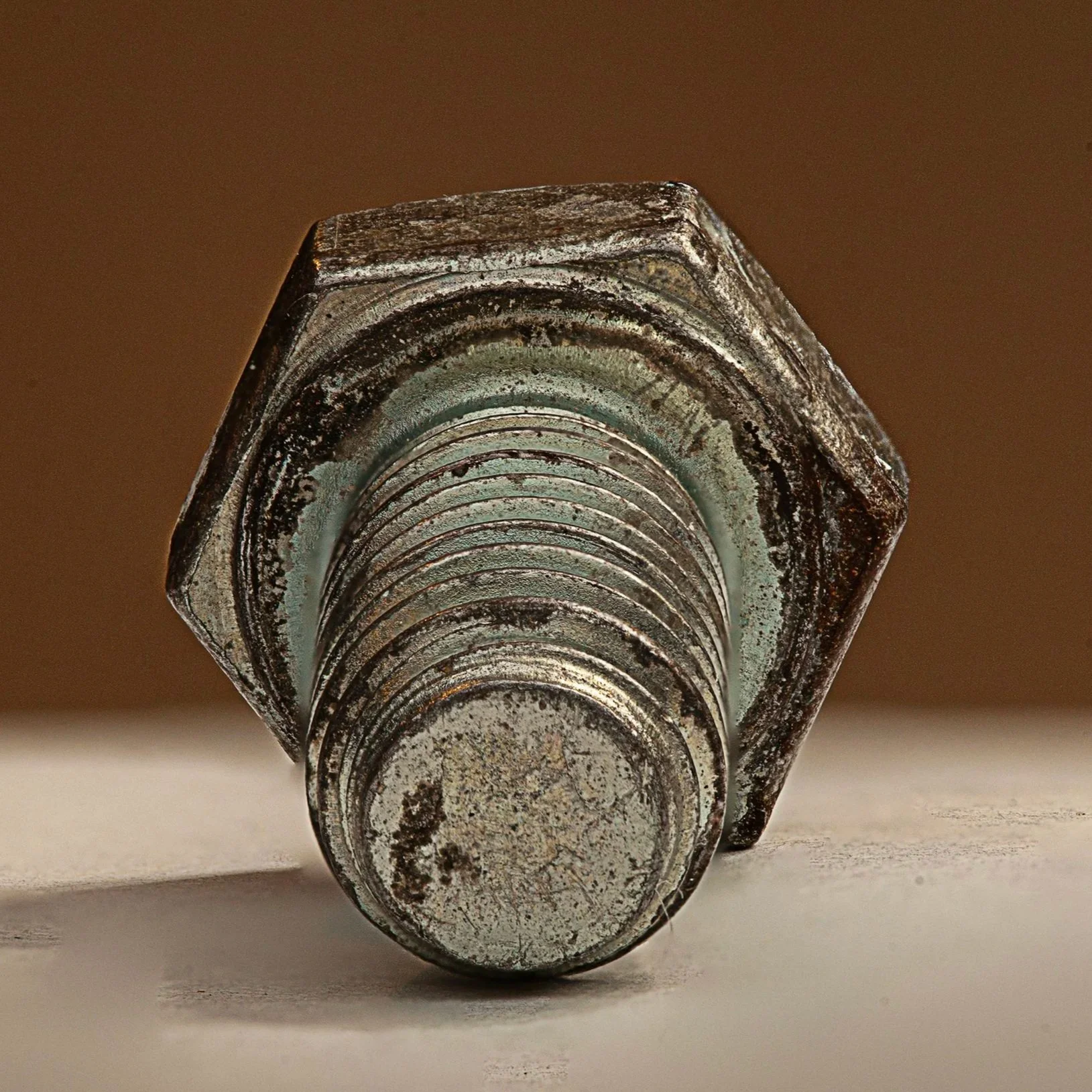
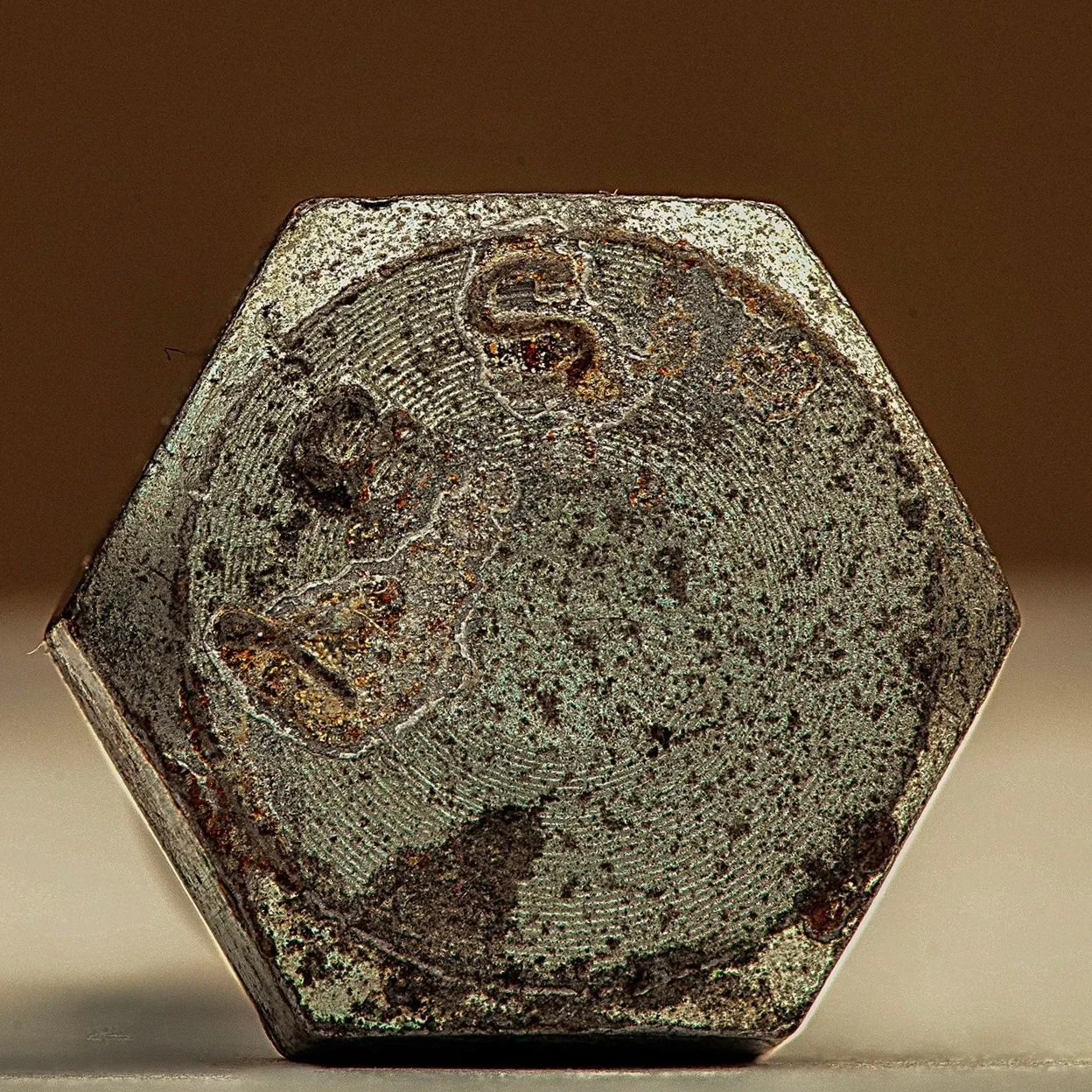
Figure 8 - Presser Foot
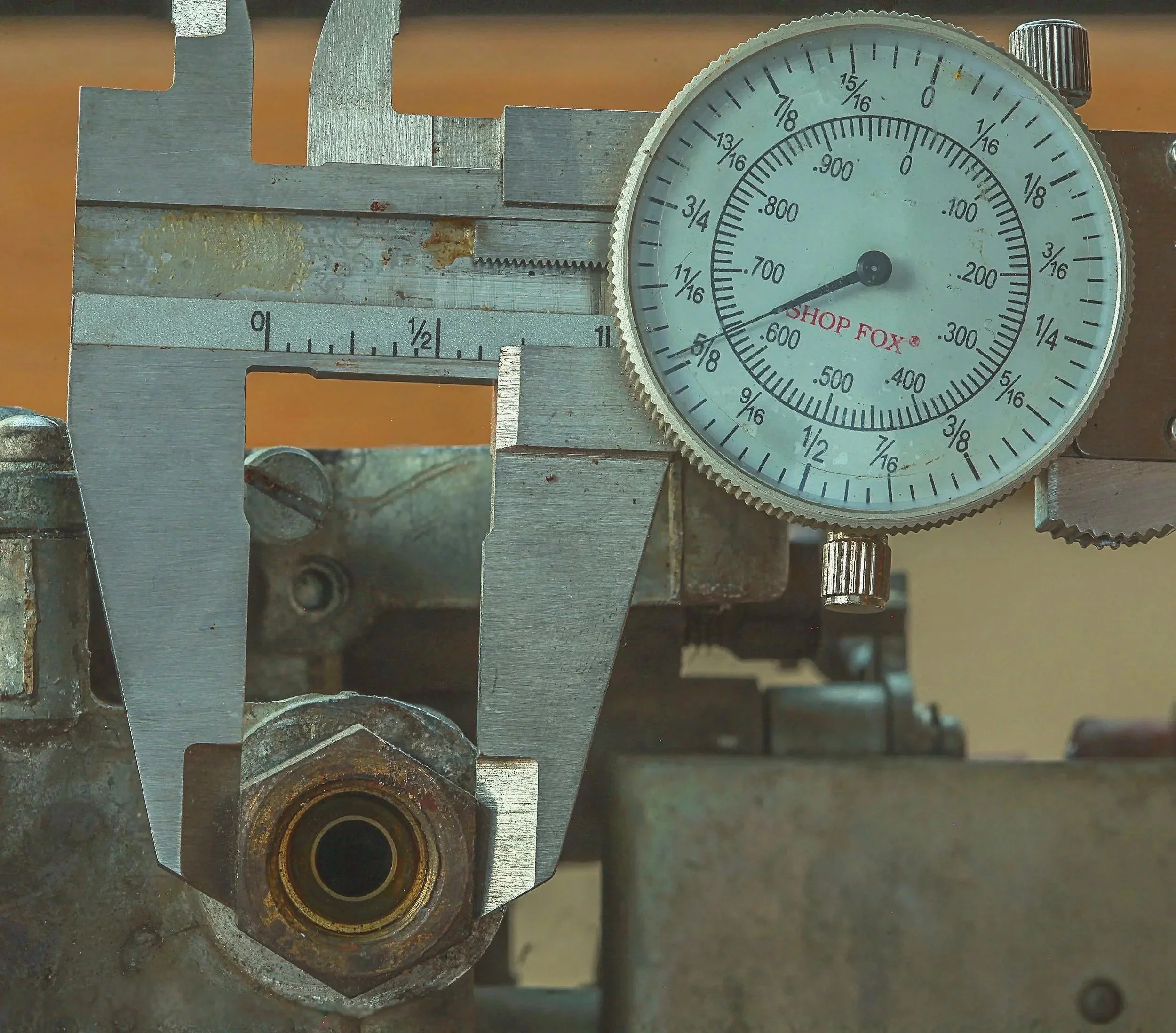
External Fastener Head Dimensional Inspection Study
Imaging Objective
Document the external fastener head measurement using precision calipers.
Imaging Methodology
High-resolution macro imaging with diffused lighting to capture fastener geometry and measurement reference.
Visual Observations
• Hex head geometry intact
• Measurement reference visible
• Surface oxidation on hex faces
Engineering Interpretation
Surface corrosion indicates environmental exposure while the fastener geometry remains structurally intact.
Use Case
Supports dimensional inspection and engineering component evaluation.
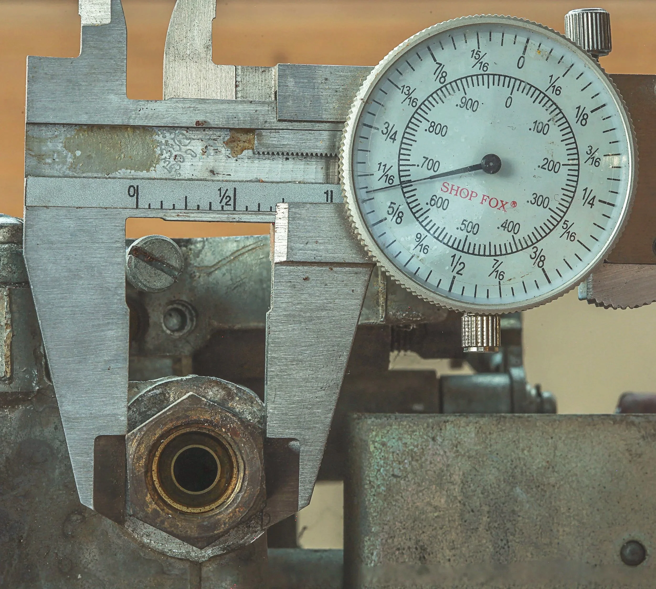
External Fastener Head Measurement – Caliper Inspection
Internal Thread Dimensional Inspection Study
Imaging Objective
Document the internal thread diameter and condition of a threaded fastener during dimensional inspection.
Imaging Methodology
High-resolution macro capture with diffused lighting to maintain clarity of thread geometry and measurement markings.
Visual Observations
• Internal thread opening clearly visible
• Thread geometry intact
• Surface oxidation around fastener head
Engineering Interpretation
Observed corrosion consistent with environmental exposure. The thread structure appears intact.
Use Case
Supports dimensional verification and fastener inspection documentation
maging Methodology
Natural light was used to minimize glare on the caliper dial and metallic surfaces. The camera was stabilized on a tripod with a macro focusing rail, and a three-frame focal bracket was captured to maintain clarity across the fastener geometry and measurement markings. A remote timer was used to eliminate vibration during capture.
Internal Thread Diameter Inspection – Caliper Measurement
Controlled Lighting on Metal
Metallic surfaces present unique lighting challenges due to their reflective properties and varied surface finishes. These images demonstrate controlled lighting techniques used to reveal surface texture, stamped markings, corrosion, and component geometry for inspection and documentation.
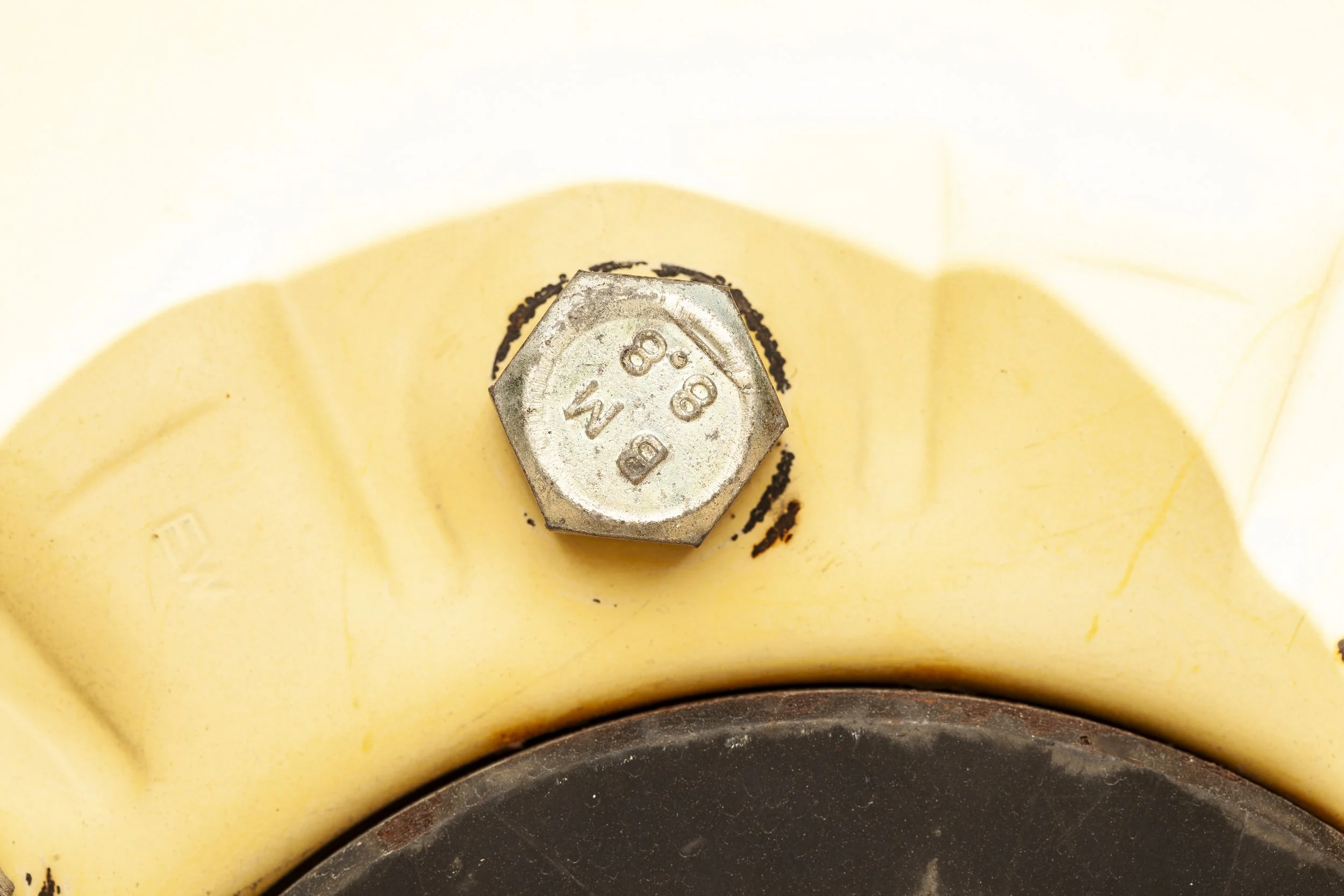
Purpose
Document stamped identification markings and surface finish on a hex head fastener mounted to a polymer component.
Technique
High-magnification macro capture using controlled directional lighting to emphasize surface texture and stamped characters while minimizing reflective glare from the metal surface.
Testing Notes
Lighting angle was adjusted to maintain legibility of the stamped grade markings (“8.8”) and manufacturer identification while preserving accurate representation of the surrounding polymer material. The controlled lighting setup ensures clear visibility of the fastener head geometry and surface condition for inspection documentation.
Purpose
Capture the interface between a domed metal fastener and surrounding polymer component to evaluate surface condition, markings, and material transitions.
Technique
Macro imaging with diffused directional lighting to control reflections on the curved metal surface and reveal stamped markings and surface wear.
Testing Notes
Lighting was configured to highlight the curvature of the fastener head while preserving detail in the adjacent plastic structure. This approach improves visibility of the fastener’s stamped identification marks and helps document the relationship between the metal fastener and the molded polymer component.
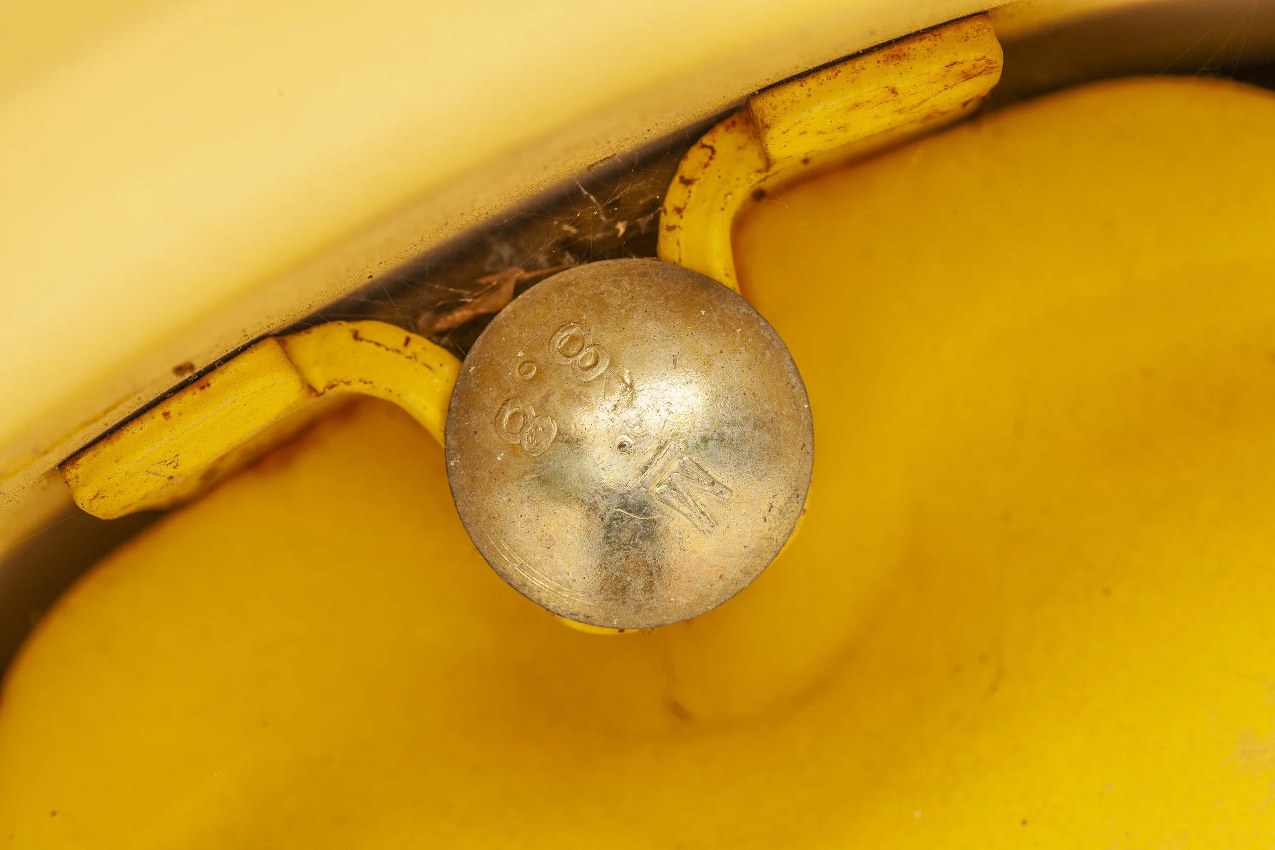
Figure 7 – Domed Fastener Head and Polymer Interface (Controlled Lighting Study)
Controlled Lighting on Glass
Transparent materials present unique lighting challenges due to their reflective and refractive properties. These images demonstrate controlled backlighting techniques used to reveal geometry and surface contours in clear materials.
Image 1 (Broken / irregular glass rim)
Purpose
Demonstrate controlled backlighting techniques used to define the edges and geometry of transparent materials.
Technique
Backlit macro imaging with controlled light positioning to create edge highlights while maintaining a dark background for contrast.
Testing Notes
Lighting placement was adjusted to emphasize the glass rim geometry and irregular contours while minimizing internal reflections. This method allows the outer edges of transparent materials to be clearly defined for documentation or inspection.

Figure 8 – Transparent Glass Geometry Under Controlled Backlighting
Image 2 (Martini glass)
Figure 9 – Reflective Glass Surface with Controlled Edge Lighting
Purpose
Capture the structural geometry of a transparent glass object using controlled lighting to reveal edge definition and material contours.
Technique
Backlighting combined with controlled side illumination to create specular edge highlights that outline the form of the glass.
Testing Notes
Lighting intensity and angle were balanced to prevent glare while preserving clear visibility of the glass silhouette and reflective surfaces.

Figure 9 – Reflective Glass Surface with Controlled Edge Lighting
Camera: Canon EOS 5D Mark IV
Lens: 2× Macro Lens
Exposure: ISO 100 • f/13 • 1/160 sec
Focus Method: 12-frame extended depth-of-field macro stack
Lighting: Rear strobe with softbox for transmitted light; front white flags positioned ~45° to control edge highlights and reduce glare
Stabilization: Tripod-mounted camera • Remote release
Processing: Focus stack composited in Adobe Photoshop with tonal normalization applied. No structural alterations performed.
Image Specifications – Insect Macro Study (Bees & Flies) – Outdoor Surface & Behavior Documentation
Camera: Canon EOS 5D Mark IV
Lens: 2× Macro Lens
Exposure Settings:
ISO: 200 (elevated to accommodate subject movement and variable ambient light)
Aperture: f/13 (to preserve depth-of-field across body segmentation, wings, and surface texture)
Shutter Speed: 1/250 sec (to arrest motion from live insect activity)
Lighting:
Predominantly natural daylight illumination
Supplemental on-camera flash with Cygnustech diffuser used as controlled fill to stabilize exposure and reveal micro-surface detail
Diffusion applied to reduce specular highlights on wings and exoskeleton surfaces
Stability:
Tripod-mounted
Short burst sequences to maintain alignment for partial stacking
Fixed working distance maintained during focus shifts


Figure 10 – Insect Structural Detail Under High-Magnification Macro
Purpose
Document fine structural features of a small biological subject to demonstrate high-magnification imaging capability and texture resolution at micro scale.
Technique
High-magnification macro imaging with controlled natural lighting to maintain clarity across the insect’s body, appendages, and surrounding floral structures.
Testing Notes
The capture emphasizes the visibility of fine hairs, joint structures, and body segmentation while maintaining background separation. This type of macro imaging demonstrates the ability to document extremely small structures with inspection-level clarity.
Purpose
Capture the structural geometry and surface texture of a small biological subject to demonstrate precision macro imaging and fine detail rendering.
Technique
High-magnification macro capture with controlled depth-of-field and directional lighting to highlight wing structure, body segmentation, and surface texture.
Testing Notes
Lighting and focus were balanced to maintain clarity across the insect’s wings and thorax while preserving separation from the surrounding floral background. The resulting image demonstrates the ability to document complex small-scale structures.
Click here to return to
Figure 11 – Wing Structure and Surface Texture (Macro Detail Study)