Surface Wear & Failure Analysis
Composite Friction Surface – Material Degradation Study
Purpose
Document the surface condition, particulate distribution, and structural degradation of a composite friction material to support inspection, failure analysis, and material performance evaluation.
Visual Observations
Composite Material Structure
The surface appears to be a composite friction material composed of a lighter matrix with embedded darker particulate inclusions.
These particles may represent metallic fragments, carbon/graphite material, or ceramic fillers, which are commonly used in friction composites.
Surface Degradation
The surface shows significant texture breakdown, including:
pitting
particle loss
micro-void formation
Several areas display irregular cavities, suggesting localized material separation or wear.
Particulate Distribution
Dark speckled particles appear unevenly distributed throughout the material matrix.
Some particles appear partially exposed or fractured, indicating wear progression or mechanical abrasion.
Edge Condition
At the upper boundary, the transition between materials shows a rough interface, suggesting possible separation between layers or different material zones.
Foreign Debris
Fibrous debris and organic contamination are present on the surface.
These contaminants likely originate from environmental exposure or operational debris accumulation.
Material Wear Indicators
Several wear indicators are visible:
• Particle pull-out from the composite matrix
• Micro-fracturing around embedded particles
• Localized pitting and void formation
• Surface contamination and debris accumulation
These conditions are consistent with mechanical abrasion and friction-related wear processes.
Engineering Interpretation
The observed wear characteristics suggest a progressive degradation of the composite friction surface, potentially caused by:
sustained mechanical friction
particulate abrasion
environmental contamination
thermal cycling or material fatigue
The pitting and particle pull-out may indicate matrix weakening, where embedded particles lose structural support and detach from the surface during operation.
Imaging Methodology
Capture Method
Macro photography with directional lighting to emphasize surface relief and particulate structure.
Technique
High-magnification macro capture
Controlled directional lighting to reveal texture and pits
Stabilized camera system for micro-detail clarity
Lighting was positioned to produce low-angle highlights, increasing visibility of surface irregularities and material breakdown.
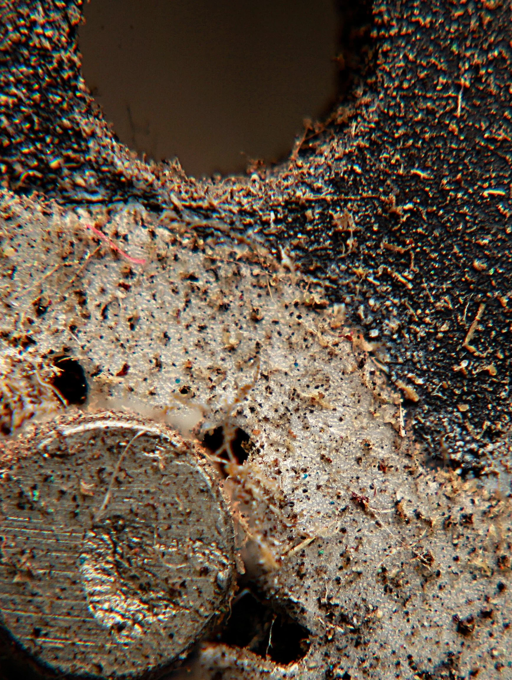

Figure 4: Threaded Fastener – Corrosion & Surface Wear Study
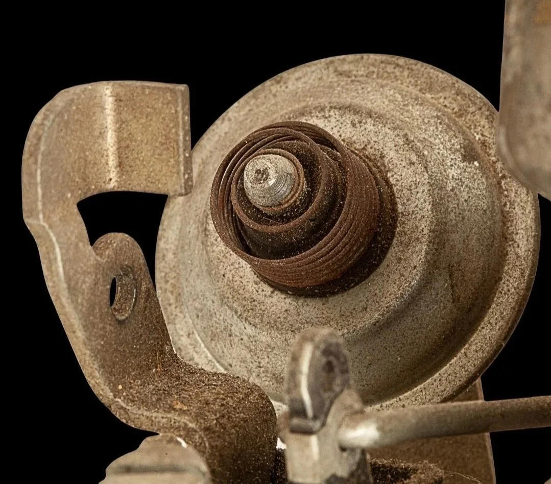
Figure 5 – Corroded Pulley Assembly (Macro Inspection)
Figure 3 – Composite Friction Surface Wear (Macro Inspection)

Surface Wear & Failure Analysis
Metal Surface Corrosion – Material Degradation
Purpose
Document corrosion patterns for engineering analysis and quality review.
Technique
Macro capture with directional lighting to reveal oxidation texture and surface irregularities.
Engineering Value
Useful for durability studies, supplier quality investigation, and failure analysis documentation.

Figure 6 – Spring-Loaded Fastener Assembly (Macro Inspection)
Image Specifications
Camera: Canon EOS 5D Mark IV
Lens: 2× Macro Lens
Exposure: ISO 100 | f/13 | 1/160 sec
Capture: 18-frame focus stack for full depth-of-field across threads, hex head, and corrosion areas
Lighting: Cygnustech-diffused Speedlite
Stability: Tripod, macro focusing rail, remote timer
Processing: Focus stack composited in Adobe Photoshop with tonal normalization. No structural alterations applied.
Threaded Fastener Assembly – Macro Failure Analysis Documentation
Component: Threaded fastener with integrated washer
Application: Mechanical assembly fastener (automotive / power equipment–type hardware)
Study Type: Non-destructive visual inspection (macro imaging)
Imaging Objective
Document the surface condition, thread integrity, and material state of a threaded fastener recovered from service or storage to support failure analysis, corrosion assessment, and engineering evaluation.
Imaging Methodology
High-resolution macro photography was performed using diffused strobe illumination to control specular highlights on metallic surfaces. Multi-frame focus stacking was applied to achieve full depth-of-field across thread geometry, washer interface, and fastener head features. Imaging was conducted in an as-received condition prior to cleaning or mechanical alteration.
Observations
Thread geometry appears intact with no evidence of shear failure or thread stripping.
Surface oxidation and discoloration are present across thread faces and washer surfaces, consistent with environmental exposure or long-term storage.
Localized surface pitting and texture variation observed along the threads.
Washer exhibits uneven wear patterns and surface contamination.
No visible cracking, fracture, or gross deformation of the fastener head or threaded section.
Engineering Interpretation
Visual evidence suggests material degradation driven by corrosion and environmental exposure rather than mechanical overload or installation-related failure. Thread engagement features remain structurally intact, indicating the fastener likely retained functional integrity prior to removal. Observed surface condition may contribute to increased friction, torque variation, or reduced service life if reused.
Use Case
Images used to support:
Non-destructive failure analysis
Corrosion and surface condition assessment
Root-cause hypothesis development
Engineering documentation and teardown records
Notes
This documentation does not include dimensional measurement, torque testing, or metallurgical analysis. No digital modifications affecting structural interpretation were applied beyond focus stack compositing and tonal normalization.
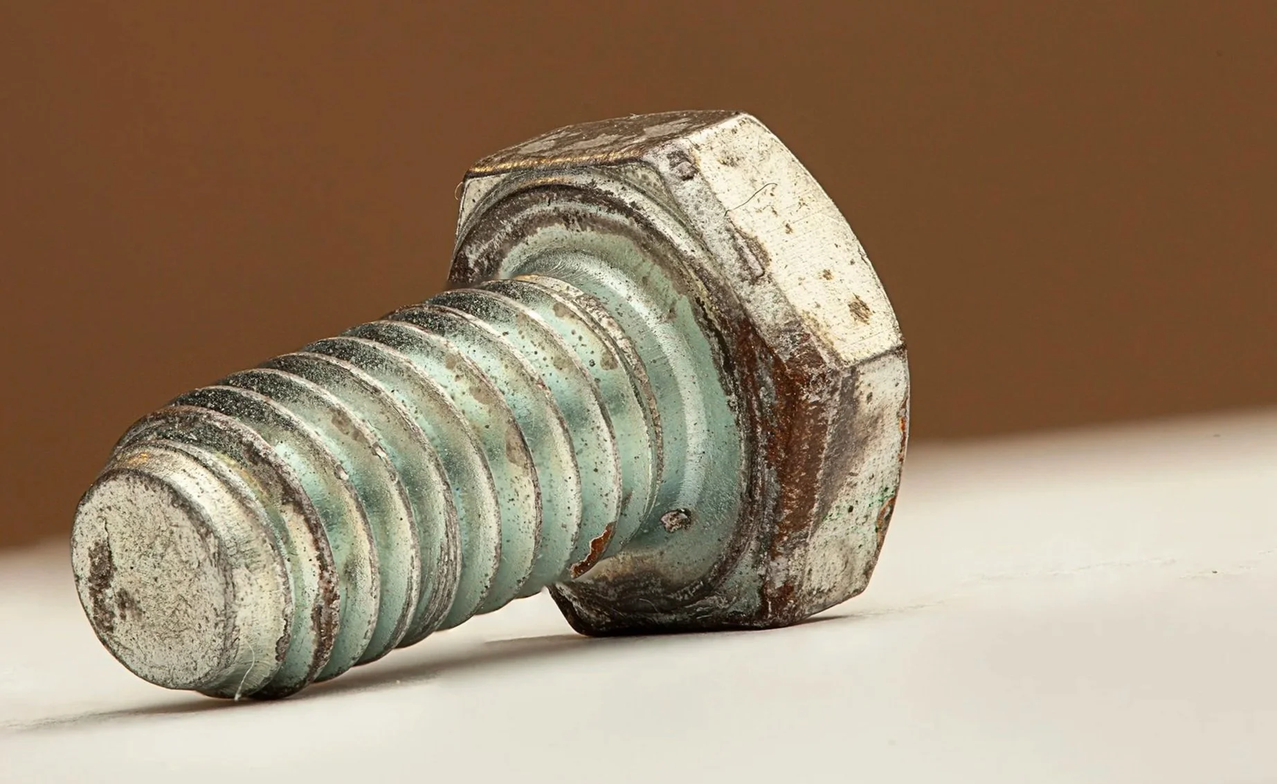
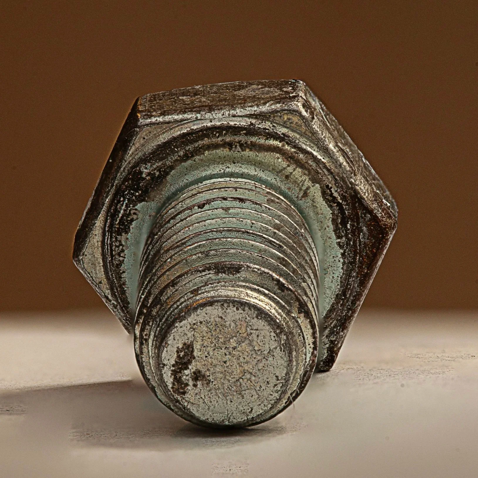
Figure 7 - Hex Head Bolt (Macro Inspection)
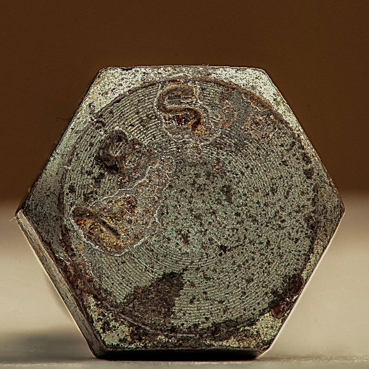
Image Specifications – Hex Head Bolt Macro Surface Condition & Corrosion Documentation
Camera: Canon EOS 5D Mark IV
Lens: 2× Macro Lens
Exposure Settings:
ISO: 100
Aperture: f/13 (selected to preserve depth-of-field across hex head geometry, thread profiles, and corrosion features)
Shutter Speed: 1/160 sec
Focus Stacking:
Number of Frames: 18 images (to maintain full depth-of-field across threads, hex faces, and localized corrosion)
Lighting:
Cygnustech-diffused on-camera flash (Speedlite)
Tripod-mounted camera
Macro focusing rail for controlled focus advancement
Remote release / timer to eliminate vibration
Processing:
Focus stack composited in Adobe Photoshop
Tonal normalization and clarity adjustments applied for accurate surface and corrosion representation
No retouching or structural alteration applied

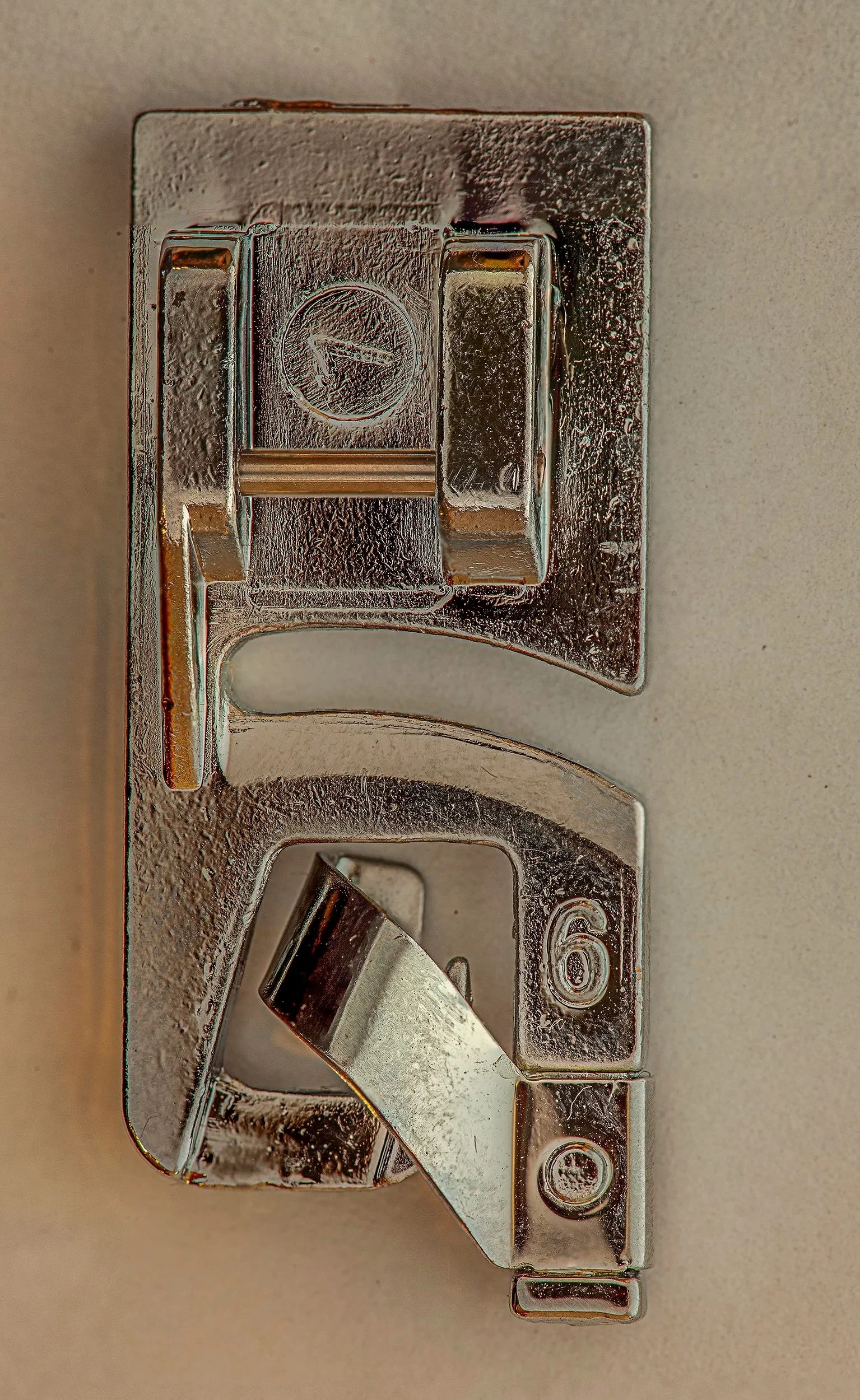
Image 8 - Rolled Hem Sewing Machine Foot
Rolled Hem Sewing Presser Foot – Macro Surface Condition & Component Documentation
Component: Rolled hem sewing presser foot
Material: Stainless steel with nickel or chrome plating
Application Context: Sewing machine attachment for producing precise rolled hems in fabric
Study Type: Non-destructive visual inspection (macro imaging)
OEM Context: Stellantis-style engineering documentation
Imaging Objective
Document the surface condition, attachment integrity, and wear characteristics of a rolled hem presser foot in as-received condition to support component evaluation, serviceability assessment, and quality inspection. Imaging captures contact surfaces, guide channels, and plated finish without mechanical manipulation that could alter original condition.
Imaging Methodology
High-resolution macro photography was performed using controlled, diffused strobe lighting to manage reflections on metallic surfaces. Multi-frame focus stacking was applied to preserve full depth-of-field across the foot base, guide slot, and heel surface. Imaging was conducted prior to cleaning or mechanical handling to preserve original condition and evidence of use or wear.
Visual Observations
Base and guide surfaces exhibit minor wear along fabric contact areas, consistent with operational use.
Plated finish remains largely intact with localized scratches and slight dulling of high-contact zones.
Screw threads and attachment points are intact with minimal coating loss; no stripped threads observed.
Guide channel shows minor micro-abrasions consistent with fabric friction during hemming operations.
No structural deformation, cracks, or catastrophic material failure observed.
Engineering Interpretation
Observed conditions suggest gradual surface wear consistent with standard operational use rather than acute damage. Minor scratches and coating dulling may minimally affect fabric glide and hem precision but do not compromise structural integrity. Visual evidence supports continued use or cleaning-based maintenance; further functional testing may be warranted if hem quality is degraded.
Use Case
Images support:
Non-destructive component inspection
Operational wear assessment
Quality control and serviceability review
Reference for replacement evaluation
Notes & Limitations
This documentation reflects surface-level visual analysis only. No dimensional metrology, hardness testing, or friction analysis was performed. Image processing was limited to focus stack compositing and tonal normalization; no alterations affecting structural interpretation were plied.
Image Specifications –
Sewing Machine Foot Macro Study
Camera: Canon EOS 5D Mark IV
Lens: Macro lens 100mm macro
Exposure Settings:
ISO: 100
Aperture: f/11 (to ensure full depth of field across the foot)
Shutter Speed: 1/160 sec
Focus Stacking: 26 images
Lighting: Macro Photography Flash Diffuser with Speedlite Flash Diffuser Softbox to manage harsh reflections and sculpt highlights. Soft diffused lighting to prevent blowouts while highlighting surface textures and wear
Stability: Tripod-mounted; timer; macro real
Processing: Focus stack blended in Adobe Photoshop; contrast enhanced to reveal surface damage without clipping highlights
Click here to return to the portfolio pages